Hybrid and electric vehicle technology has seen rapid development in recent years. The motor and generator are at the heart of the vehicle drive and energy system and often utilise expensive rare-earth permanent magnet material.
Existing hybrid and electric vehicles, such as Toyota Prius, Chevrolet Bolt, Nissan Leaf, and BMW i3 all use high-energy-density permanent magnet (PM) machines for electric propulsion. The magnetic material is usually sintered neodymium–iron–boron (NdFeB).
Squirrel cage induction motors (IM) have been successfully used in electric vehicles (GM and Tesla) and commercial vehicles (buses and trains). They are much cheaper and more robust although they can struggle to get the same torque density.
Currently, the interior permanent magnet synchronous motor (IPMSM) is the most common machine in use, but manufacturers are keen to develop drive motors with much lower magnet content. High torque density and efficiency are required, as well as a wide constant power range.
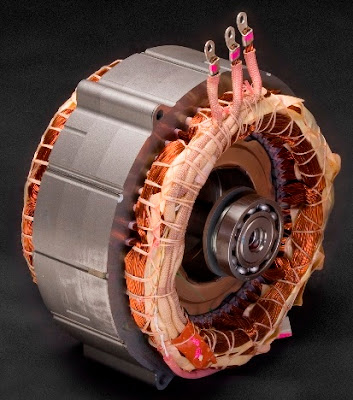
In an effort to improve the torque density of automotive induction motors Evans Electric have developed a double stator, copper rotor, axial flux induction motor. (AFIM) Like a typical squirrel cage induction motor, the AFIM eliminates the need for rare-earth permanent magnets entirely, yet matches the IPMSM for torque density and energy efficiency.
Axial Flux Torque Density (Nm/L)
The earliest electrical machines were axial flux motors with the first prototype built by Michael Faraday in 1831. Axial flux machines [Figure 1] (aka. Pancake motors) offer high torque and power density values. A double stator architecture offers the highest torque density coupled with balanced axial forces. Further, the short axial length and solid-core copper rotor construction (patented by Evans Electric) further enhance torque density values when compared to radial flux motors.
Figure 1
Conventional radial flux motor geometry [Figure 2] requires azimuthal travel of magnetic flux through the rotor. Azimuthal flux path volumes result in substantial parasitic eddy current losses unless laminates are used. A double stator, single rotor axial flux geometry [Figure 1] has a shorter flux return path that inherently avoids parasitic eddy current losses and results in a much smaller total rotor volume.
For example, the Telsa Roadster AC induction motor outputs similar torque values but is dimensionally 3x the volume of the Evans Electric AFIM which was designed to achieve output torque density of 100 Nm/L.
AFIM torque density can be further increased by reducing the impedance of the machine and increasing the bar number. Typical pole numbers are 6 to 8 while the use of high rotor bar number increases torque and decreases torque vibration.
The use of copper in the disc rotor lowers rotor resistance which improves efficiency but can restrict starting torque.
To obtain high efficiency the machine should be running at low slip so that higher pole number is usually required along with low rotor resistance. However, this can restrict the starting torque. This means that the input impedance as a whole needs to be low which does lead to high input current. However, to get high power factor the input reactance should be low compared to the input resistance. This leads to the need for compromise.
Figure 2
In industrial motors deep bars or double cages can be used but these options are not available in an axial flux design. However, the solid steel rotor aids the starting torque since this appears as an effective high resistance rotor. The maximum torque can be increased by reducing the impedance of the machine and increasing the bar number.
Efficiency – Comparing IM and PM Machines
Efficiency is important for hybrid electric vehicle drive motors. With energetically ‘free’ excitation, low fundamental reactance and the ability to have a high pole count, permanent magnet machines can be extremely light in weight and highly efficient. This is particularly true for industrial applications that involve a restricted speed range, meaning a fixed terminal voltage.
In such applications the design strategy is to build in a high internal flux (which permanent magnets do admirably), so that torque is produced with minimal input current. Then efficiency is high, and the motor can be made light in weight and physically small.
Traction motors for applications such as automotive, are different in that they must operate over a wide speed range. Automotive traction motors require a certain torque (‘base torque’) at low speeds, up to what is called the ‘base speed’, and then a roughly constant power over a speed range from the base speed to a maximum speed that might be several times the base speed. In traction motor applications using wound field DC machines, this torque-speed characteristic is accomplished using what is called ‘field weakening’, or simply reducing field current at high speed.
Prius THS II
The requirement for performance over a relatively wide speed range can force some compromises in permanent magnet motor design. It is not possible to turn down the permanent magnet flux to control terminal voltage at high speed. It is possible, however, to counter the permanent magnet flux with armature current, and this can be done in permanent magnet fields if the permanent magnet flux is not too strong.
So permanent magnet machines built for wide speed range operation generally have relatively weak permanent magnet excitation. Then it is necessary to build a high degree of saliency into the machine so that torque can be produced by interaction of terminal current with that saliency. Thus the permanent magnet machines built for automotive traction operation do not have all of the attractive features one would expect of permanent magnet machines.
At low speed and high torque they do not really operate as permanent magnet machines: they are more akin to synchronous reluctance machines, using the interaction between saliency and (large) terminal currents to produce torque. At high speeds they employ much of their armature current capability to counter the permanent magnet flux, and this negatively affects efficiency at high speed. Such machines can be made to be quite efficient at relatively low torque level and intermediate speed.
The Evans Electric AFIM achieves maximum efficiency of 96%.
Evans Electric AFIM
Effective Efficiency of Traction Motors
To understand the impact of motor losses, including PM drag loss on actual machine operation, we now attempt to evaluate the effective efficiency of a machine with a realistic operating scenario.
Recognise that losses in machines come from two sources. First, acceleration force requires current in the windings, so resistive losses occur. Second, rotational speed produces loss from friction, windage and, most important, core loss.
In permanent magnet machines there is always flux present so that there will always be rotational losses. Induction motors can be de-excited so that core loss can be ‘turned off’ when the motor is not producing torque.
In actual operation as a traction motor the induction machine is more efficient and has a substantial advantage because it can be de-excited when it is not producing torque, eliminating electrical loss in that condition. Since those losses are present only when, and to the extent, the induction motor is producing torque, hybrid vehicles are expected to be more efficient when induction machines are used for the drive motor.
Cost Analysis
Rare-earth material costs can be up to several orders of magnitude more expensive than common steel and copper typically found in IM. The reduced volume of an AFIM further lowers material costs compared to a conventional radial flux IM. A reduction in motor material costs not only improves Hybrid and electric vehicle profitability but also facilitates the long term trend towards multi-motor EV powertrain architectures ie. twin and quad motor AWD.
Source: Evans Electric


